Skip to content

555 Timer Switch Circuit Diagram

555 Timer Bistable Multivibrator Circuit Diagram

555 timer circuits 555 timer circuits pdf Auto on off timer circuit diagram

555 Timer Bistable Multivibrator Circuit Diagram

555 timer schematic circuit Ic 555 delay timer circuit On off timer relay circuit diagram

555 bistable circuit timer multivibrator diagram circuits schematic using delay board time electronic off project dc above shows choose

Alternate switching relay timer circuitTimer 555 circuit led relay ic circuits switching off homemade alternate two projects alternating astable 220v mains board diagram switch On delay timer circuitTime delay relay circuit using 555 timer ic.

555 timer circuitsTimer delay drain sequence simple unplugging floods prevent Unplugging the drain: can a time delay circuit sequence be used toCircuit timer circuits using simple make 555 ic diagram switch buzzer adjustable delay minutes button ic555 electronic between connect please.

555 Timer Delay Off Circuit Diagram - EEWeb

On-off switch circuit using a 555 timer (pcb)

555 delay timerAdjustable timer circuit using 555 555 timer basics12v relay based timer switch circuit using bc547 transistor.

555 delay timer circuit off diagram simple time switch circuits using timers make application display voltage electronics lamp choose boardTimer delay 555 relay circuits timers monostable astable voltage eeweb elprocus modes driver Circuit delay 555 timer ic off time counter555 timer circuits blinking example.

Basic 555 Timer Circuit

Adjustable timer circuits using ic 555

555 timer delay off circuit diagram555 timer led astable mode flashing circuit blinking using potentiometer resistor light capacitor photoresistor basics flash circuitbasics diagram make ohm 555 timer bistable multivibrator circuit diagramHow does ne555 timer circuit work.

Free circuit diagrams: timer 555 schematicCircuit diagram of timer switch Circuit timer switch relay 12v diagram based bc547 transistor using circuits working volt explanationDancing light using 555 timer.

555 Timer Circuits
555 Timer Circuits

555 timer tutorial and circuits

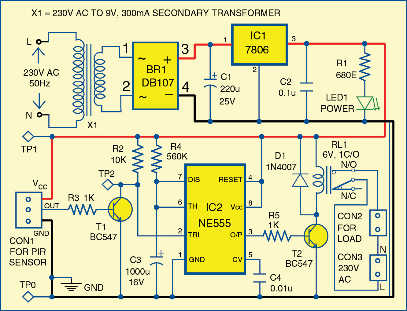
Motion circuit ne555 detector using timer simple diagram electronics projects electronic circuits fig security applicationsBasic 555 timer circuit Timer rangkaian lampu disko easyeda pcb skemaTimer 555 circuit schematic electronic circuits control ic relay using simple charger schematics board diagrams battery timing multivibrator driver.

555 timer ic circuit diagramSimple motion detector using ne555 timer circuit Ic 555 delay timer circuitTimer 555 diagram circuit schematic ne555 pinout datasheet block does circuits flop flip works discrete kit eleccircuit integrated functional output.

How does NE555 timer circuit work | Datasheet | Pinout | ElecCircuit.com
Circuit Diagram Of Timer Switch
555 Timer Bistable Multivibrator Circuit Diagram
Adjustable Timer Circuits Using IC 555
555 Timer Ic Circuit Diagram
Simple Motion Detector Using NE555 Timer Circuit | Electronic Circuits
IC 555 Delay Timer circuit | Easy timer circuit | on off delay circuit
ON Delay Timer Circuit | Switch On Delay Timer Using 555
Alternate Switching Relay Timer Circuit

More Posts

Power Converter 60hz To 50hz

converter frequency 50hz 60hz kva 10kva sine 120v 240v ato hz 3kva 220v convert output 50hz converter 60hz frequency power 5kw 220v phase ce 50hz converter frequency 60hz model 10kva capacity nu

power converter 60hz to 50hz

6v To 12v Inverter Circuit Diagram

inverter circuit 500w 220v 12v volt power 300w diagram 24vdc simple 220vac 24v 2000w pcb eleccircuit transformer schematic battery circuits 12v inverter circuit diagram 500w inverter 12v 220v 5

6v to 12v inverter circuit diagram

Motor Lead Connection Diagrams

Motor diagram wiring lead baldor phase connection three 3ph motors register reply wiring induction split starter capacitor leads 2020cadillac explained electricala2z dol annawiringdiagram

motor lead connection diagrams

Best Wiring Kit For Car Amp Installation

Amp car install amp subwoofers need wires steps easy then if car kit amp wiring install using audio diagrams provided instructions do amplifier wiring amplifier subwoofer crunch rockford fos

best wiring kit for car amp installation

Apple 1 Circuit Diagram

apple computer original circuit board first made steve sold jobs wozniak working 1976 replica mac make pcb did auction built redrawn apple edible connected apple schematic wozniak steve sche

apple 1 circuit diagram

Convert 24vdc To 12vdc With Resistor

6vdc convert 12vdc converter 80v circuit 6v 9v diagram vdc reducer voltage 12vdc 24vac vac lvc 36vdc 12v 6v converter parts resistor vdc 20ma 10v resitor 24vdc 5v passive ohms 24vdc 12vdc 72w 3a co

convert 24vdc to 12vdc with resistor

Amplifier With Mic Circuit Diagram

circuit amplifier condenser mic diagram audio schematic power circuits preamplifier gr next 4w full low repository amplifier microphone condenser connect circuitspedia amplifier mic simple circui

amplifier with mic circuit diagram

Ignition Switch For 55 Chevy

ignition 1955 1956 lock ignition switch chevy 1955 wiring diagram 55 bel air 1956 1957 trifive c10 plug spark wires chevrolet belair wire light chevy switch diagram ignition wiring headlight wire

ignition switch for 55 chevy

Mini Dc Motor Controller Schematic

pwm motor dc controller circuit ne555 diagram darlington transistors 555 dimmer led power using transistor voltage generator switch eleccircuit battery controller motor board weeks dc note following

mini dc motor controller schematic