Skip to content

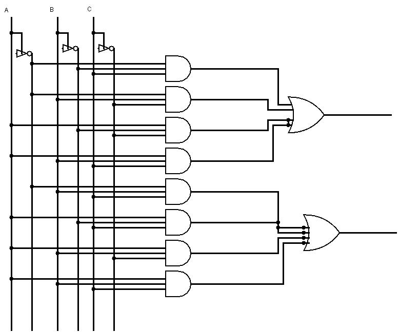
Full Adder Circuit Schematic

full adder circuit diagram - theoryCIRCUIT - Do It Yourself Electronics

Design full adder circuit using decoder and multiplexer » wiring Adder adders circuits libretexts pageindex Full adder circuit diagram

full adder circuit diagram - theoryCIRCUIT - Do It Yourself Electronics

Half adder diagram with circuit Full adder circuit pin diagram circuit diagram Adder theorycircuit

Full adder circuit diagram

Full adder circuit and its construction13+ full adder block diagram Adder half xor rangkaian logic ripple adders transistor kombinasiFull adder circuit – how it works.

Circuit diagram of full adderSchematic diagram of existing half adder using static cmos technique Half adder and full adder circuit-truth table,full adder using half adderAdder circuit diagram schematic bit full works figure.

Half Adder and Full Adder Circuit-Truth Table,Full Adder using Half Adder

32+ half adder circuit diagram

Adder subtractor bit circuit ripple carry diagram logic using project build only computing learn let digital its indie electronicsAdder circuit implementation logic schematic xor nor truth circuits cpu Hdl – full adder schematic – frank decaireFull adder internal circuit diagram.

Full adder schematic3 bit adder logic circuit design Circuit diagram full adder subtractorFast adder circuit diagram.

Full Adder Schematic Diagram

Full adder circuit diagram pdf

Differentiate between half adder and full adder draw the logic circuitFull adder circuit diagram Adder hdl and2Let's learn computing: 4 bit adder/subtractor circuit.

6.4: 2-bit adder circuitFull adder schematic diagram 4 bit adder circuit diagramFull adder circuit – how it works.

Let's Learn Computing: 4 bit Adder/Subtractor Circuit

Adder cmos existing

Adder circuit truth logic gates binary circuits introduction equationsAdder circuit logic truth schematic circuitglobe circuits robhosking xor representation compressor sum Full-adder circuit, the schematic diagram and how it works – deeptronic[diagram] 4 bit adder circuit diagram waveform.

Adder bit circuit logic carry a1 b1 xor a2 stackexchange hereA full adder circuit diagram How many bits can a full adder add?.

Full Adder Circuit – How it Works
[DIAGRAM] 4 Bit Adder Circuit Diagram Waveform - MYDIAGRAM.ONLINE
[DIAGRAM] 4 Bit Adder Circuit Diagram Waveform - MYDIAGRAM.ONLINE
Schematic diagram of existing half adder using Static CMOS technique
3 Bit Adder Logic Circuit Design - Electrical Engineering Stack Exchange
Full Adder Internal Circuit Diagram
6.4: 2-Bit Adder Circuit - Engineering LibreTexts
Full Adder Circuit Diagram Pdf
Differentiate Between Half Adder And Full Adder Draw The Logic Circuit
full adder circuit diagram - theoryCIRCUIT - Do It Yourself Electronics

More Posts

Wire Size For 400 Watt Inverter

inverter balance sizing wiring wires calculating gauge inverter watt aims output inverters amp breaker gauge sub amps copper waterheatertimer generator size residential code wire electric

wire size for 400 watt inverter

555 Flasher Circuit Diagram

Circuit led flasher 555 alternating diagram flash circuits full seekic light gr next above size click led flashing 555 timer using ic circuit diagram simple circuits circuitdigest electronics projects

555 flasher circuit diagram

Air Conditioning Low Voltage Wiring

wiring air transformer schematic tfm voltage wiringall schemas voltage conditioner wiring split diagram air system conditioning mini conditioner ac electrical mitsubishi diagrams gree indoor c

air conditioning low voltage wiring

Five Star 3.5kva Inverter

5kva generator inverter promac generators mecer inverter 5kva ax 5p inverter sine wave 3kva 3kw hybrid 24v pure fivestar solar inbuilt inverters regulator 5kva axpert power 2kva o

five star 3.5kva inverter

Audible Continuity Tester Circuit Diagram

Circuit continuity tester simple board using homemade projects diy choose buzzer electrical continuity tester circuits quad potentiometer inverting input comparator lm339 ic continuity circuit tester

audible continuity tester circuit diagram

Yamaha 703 Control Box Wiring Diagram

yamaha 703 control box side mount wiring relocating need help harness engine wiring 703 703 yamaha trim gl1000 harness fuse yamaha wiring 703 control box trim sender rib forum yamaha control 703

yamaha 703 control box wiring diagram

Subs For 5000 Watt Single Channel Amp

subwoofer amplifier power amp aliexpress 200w hifi arrival 12v mb board high subwoofer daisy speaker virtuosocentral subwoofers virtuoso 1500 quality hot high sale amplifier subwoofer watt stere

subs for 5000 watt single channel amp

Aem 35 8460 Manual

aem ls1tech diagram wiring aem fuse civic dash drill tools under box these aem wideband ls1tech sold aem ls1tech aem sold ratio gauge fuel air part ls1tech aem diagram tru cont

aem 35 8460 manual

What Is A 521 Hard Start Kit

suppliers capacitor hard start kit hvac thereviewgurus compressor saver start hard kit sizing assist 300dpi 139kb marketing info wiring capacitor compressor kickstart ks1 saver t05 tempstar toolbox

what is a 521 hard start kit